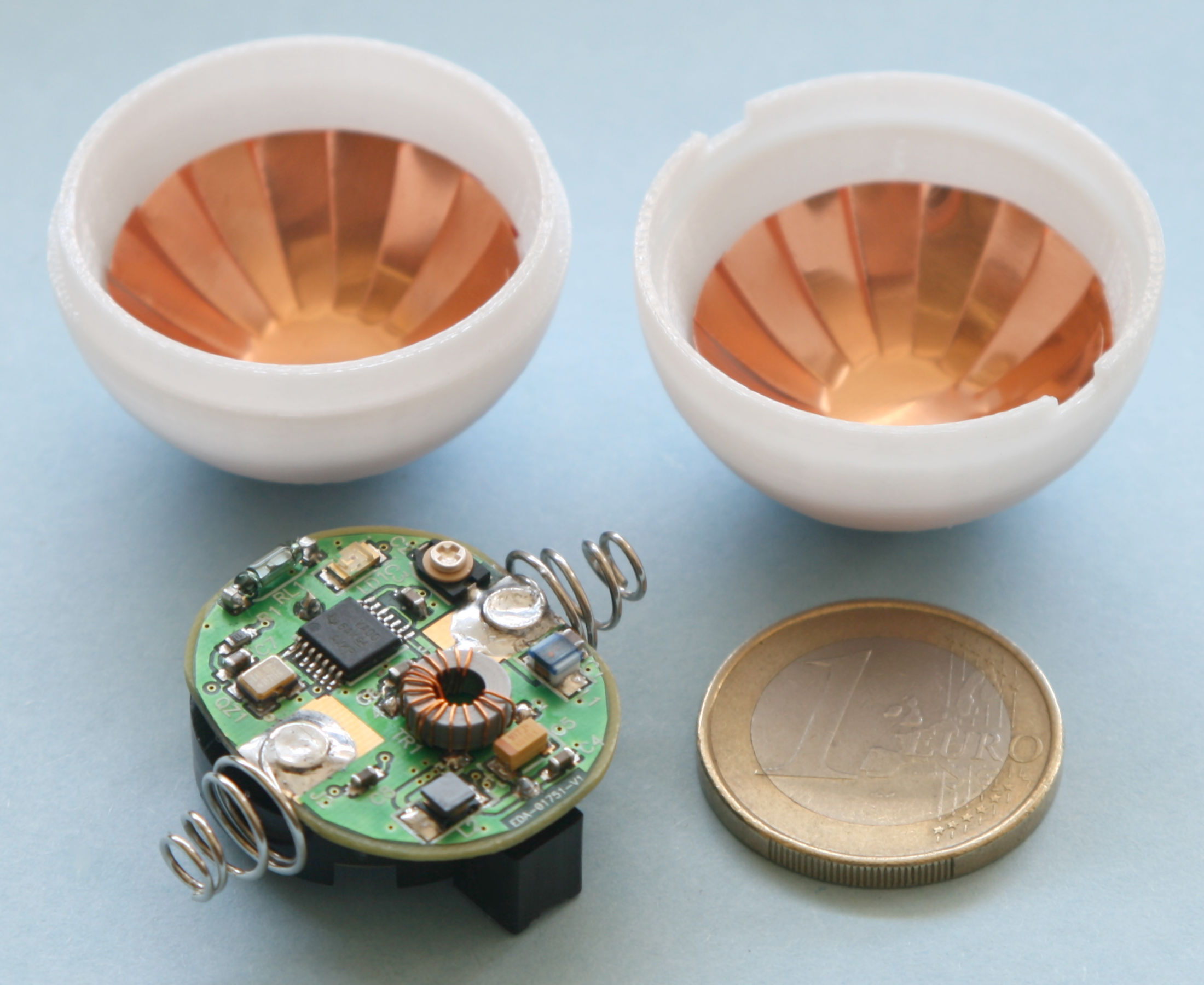
The LHC RF ball in pieces.
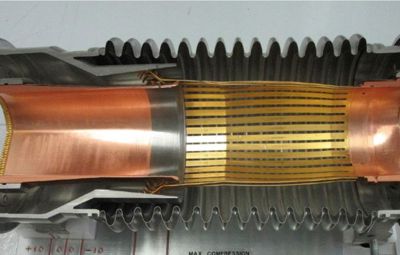
A cross-section view a plug-in module with good spring contacts.
(Fot. CERN)
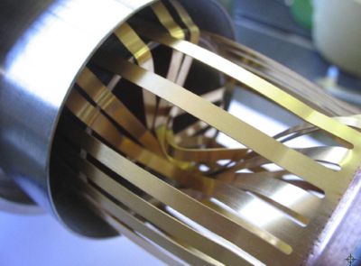
Spring contacts after buckling. (Fot. CERN)
LHC RF ball project
- Article "LHC gets the ball rolling" in the CERN Bulletin (# 41/2007, 8/10/2007)
- Description in LHC Project Report 1113 (presented at EPAC 2008 conference)
The radio-frequency (RF) ball project was started in 2007 to localise defective LHC plug-in modules (PIMs). PIMs accommodate spring contacts, which provide a bypass at each magnet interconnect for high frequency currents accompanying the circulating particles. The spring contacts were designed to slide over the PIM surface during magnet length drifts related to large temperature changes when the magnets are cycled between - 271 °C (1.9 K, their nominal operation temperature) and the room temperature, required during maintenance and upgrade periods. Unfortunately, some PIM contacts did not slide during the magnet warm-up and instead got buckled into the beam pipe aperture. The buckled contacts would be fatal obstacles for the LHC circulating beams and had to be repaired. In the LHC there are some three thousand PIMs and without a special technique all of them would have to be inspected from the outside by cutting open the magnet interconnects. This would be a very laborious, time consuming, expensive and inefficient task, as only a very small fraction of all PIMs was expected to be defective. This is why a multidisciplinary "rescue working group" was built and charged to look for alternative solutions. After a few weeks of intensive studies and tests carried by the group it was demonstrated that the defective PIMs can be localised by sending inside the LHC beam pipes a plastic ball equipped with a radio-frequency transmitter. The ball was propelled by a flow of filtered air generated in the beam pipe by dedicated vacuum pumps and it was detected by the regular LHC beam position monitors (BPMs), located every 54 m, and sensitive to the 40 MHz signal transmitted by the ball. Then if the ball encounters a defective PIM (or any other obstacle), it is known between which BPMs it got blocked and only in this area the LHC magnet interconnects have to be inspected.
Each beam pipe of each of the eight LHC sectors is tested separately. The ball is sent inside each beam pipe over some 2.8 km distance at the speed of about 2.5 m/s (9 km/h), passing through some 50 BPMs, which takes about 20 minutes. If the ball gets stopped on its way, the location is known within 54 m of the BPM distance. Then it is attempted to get the ball back to the sector beginning by reversing the air flow. If this is successful, the ball is sent again to confirm the problematic area. Then magnet interconnects from the suspicious 54 m are X-rayed to localise the obstacle and the reparation work starts. After the reparation is completed, the sector is tested again with the RF ball to find a next obstacle or to confirm that the sector both beam pipes are clear and ready to be cooled down to the cryogenic temperatures.
The LHC is tested with the RF ball each time the machine is warmed up, for example in 2013. The procedure is carried out also after all maintenance and reparation work, for example in 2014 after the long shutdown.
Summary:
| RF ball other names: | RF mole, Ping-Pong, Sputnik, Magic Ball. |
| Number of pieces built (till 2013): | 10. |
| Ball material: | polycarbonate (shock resistivity, small fragments tolerated in the LHC vacuum). |
| Ball production process: | fused deposition modelling (FDM). |
| Ball construction: | two hemispheres 2 mm thick with a lock, bounded with a cyanoacrylate glue. |
| External diameter: | 34 mm (a regular ping-pong ball 40 mm). |
| Ball weight: | 8 g (a regular ping-pong 2.7 g). |
| Total weight with the circuitry and battery: | 15 g. |
| Operational lifetime: | 50 h (450 km travel at 2.5 m/s). |
| Stand-by lifetime: | several months when switched off by an external magnetic field. |
| Transmitter "antenna": | two pieces of copper foil electrodes covering the inside the hemispheres. |
| Transmitter signal: | 20 Vpp, 30 µs bursts of 40 MHz every 2 ms. |
| Battery: | lithium 3 V, 240 mAh, Ř 20 x 3.2 mm, 3 g. |
| Circuitry: | 5 integrated chips on a 4-layer printed circuit board. |