|
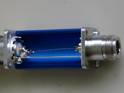
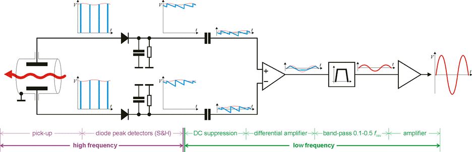
Fig. 2. The very first detector built. The input, connected directly to a PU output, is on the left.
The right connector is connected through semi-rigid coax cables to the front-end box.
The detector consists of a coaxial line high frequency transformer (the thing with the toroid), an inductor and two Schottky diodes.
The storage network is formed by the capacitance of the cable connecting the detector to the front-end box, as well as a small value capacitor.
The discharge resistor of a very large value is located in the front-end box.
These few components seen in the picture are the most important in the system.
|
|
Fig. 3. The very first prototype of the front-end electronics. It had only one processing channel (the left compartment).
On the bottom there are two differential inputs and at the top - the output.
The right compartment accommodates the power supply and control logic.
The prototype was almost as powerful as the final version with serious PCBs.
After a very good service on the SPS, the circuit shown had been modified and installed on the PS for 3D studies.
|
|
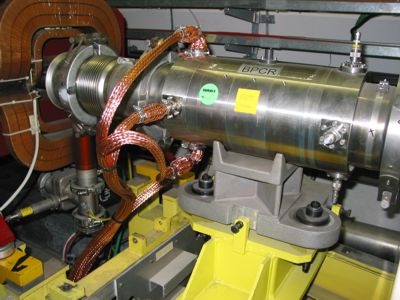
Fig. 4. The SPS 3D installation. The detector boxes, connected to a standard position stripline PU, are put inside heavy copper braids,
together with semi-rigid coaxial cables connecting the detectors to the front-end lying upon the pick-up base. The braids improve shielding of the input signals.
This is extremely important due to enormous gain of the front-end, exceeding 100 dB.
|
|
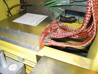
Fig. 5. The SPS 3D installation (cont.).The braids are carefully tightened on the front-end N input connectors.
|
|
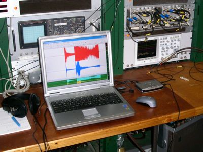
Fig. 6. A PC sound card as an excellent acquisition system. The 3D signals had been acquired with a 24 bit, 96kS/s, USB external sound card Sound Blaster Audigy 2 NX.
|
|
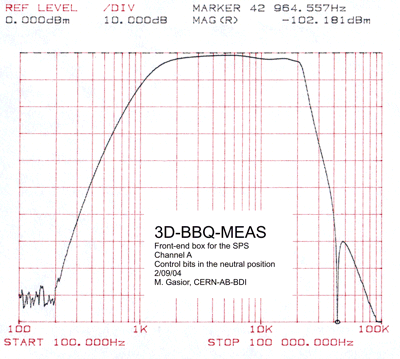
Fig. 7. The frequency characteristic of the SPS front-end. One of the advantages of the 3D method is that the filter has to be done for relatively small frequencies, for which active components have great parameters. The notch is at the revolution frequency. The filter does not contain any adjustable elements.
|
|
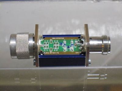
Fig. 8. For a comparison, the final version of the LHC detector with an input 450 MHz low-pass filter.
|
|
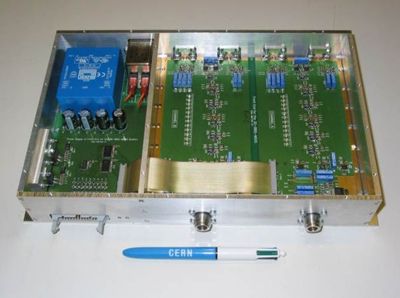
Fig. 9. For a comparison, the final version of the 3D analogue front-end. Versions for each machine are built on the same PCBs.
Only values of some components are speciffic for each machine.
|
|
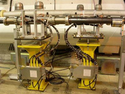
Fig. 8. For a comparison, a photograph of the operational BBQ installation in the LHC tunnel.
Two front-end boxes are seen, containing four independent channels, for both H and V planes of each LHC beam.
|
|
|