The revolution frequency (fr) was not available in the TFB room, so the signal was digitized with fixed frequency, generated internally by the SIS module. The smallest sampling rate available was 3.125 MHz, which is some 6 times higher than necessary (the highest fr, which is ca 477 kHz). For this reason there were played tricks to decrease the effective sampling rate by using averaging consecutive samples (a feature of the SIS module) or decimation (e.g. only every 6th sample is stored to decrease the sampling rate by a factor 6). In consequence, usually the effective sampling rate used was rather odd. For instance, you can use the clock of 3.125 MHz and decimation factor of 6 to have the effective sampling rate of 520.833 kHz, or use the clock of 100 MHz and average 128 consecutive samples to get the effective sampling rate of 781.25 kHz, or a mixture of the two: clock of 100 MHz, average over 64 samples and decimate by factor 3 gives the effective sampling rate of 100e6/64/3, that is 520.833 kHz. The last setting was used most of the time.
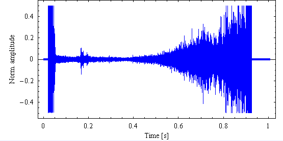
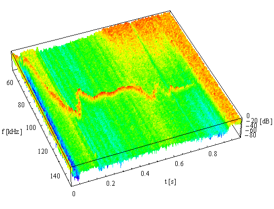
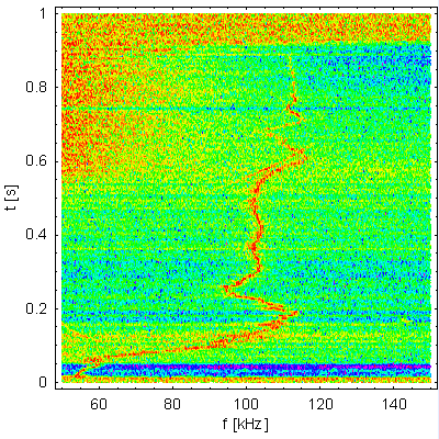
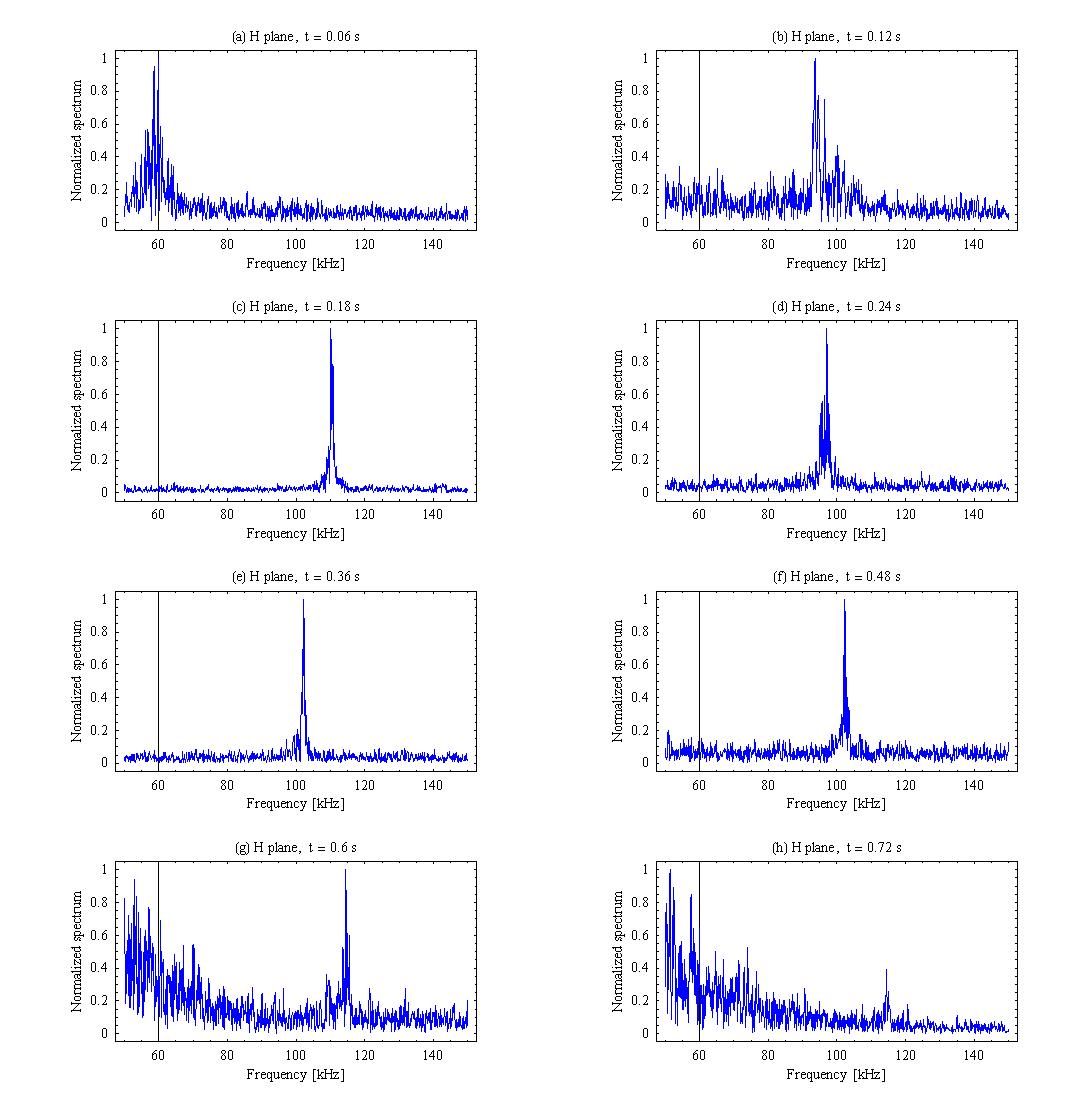
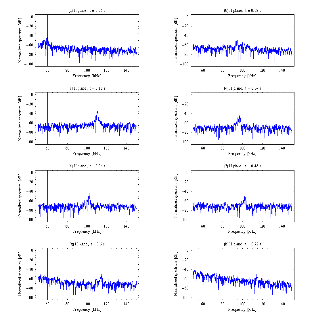
Below are tune paths seen WTHOUT ANY EXCITATION on an AD cycle. Acquisition started 20 ms before injection (on C=151). The sampling rate was about 520.8 kHz (fixed frequency). Each segment of 5208 samples (i.e. 10 ms of signal) was Hanning windowed prior to calculating their magnitude spectrum. Consecutive sample segments overlap by 50%, so on the plots there are spectra each 5 ms.
On the right it is shown signal for an AD cycle,
measured on 15/11/04 at 14h50. No excitation.
Below is the link to the WAV file, which I produced from the samples acquired. Since the betatron frequency can be at most fr/2, i.e. ca 240 kHz, a human being cannot hear it. I had to stretch the time scale by a factor of 20, reducing the highest betatron frequency by the same factor, to some 12 kHz.
Headphones are recommended to resolve different components.
Beam sound, H plane, 20-times stretched time scale, mono, ca 1MB, 26kS/s.