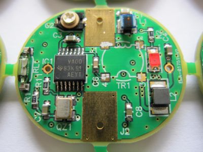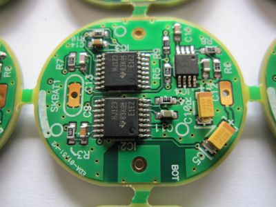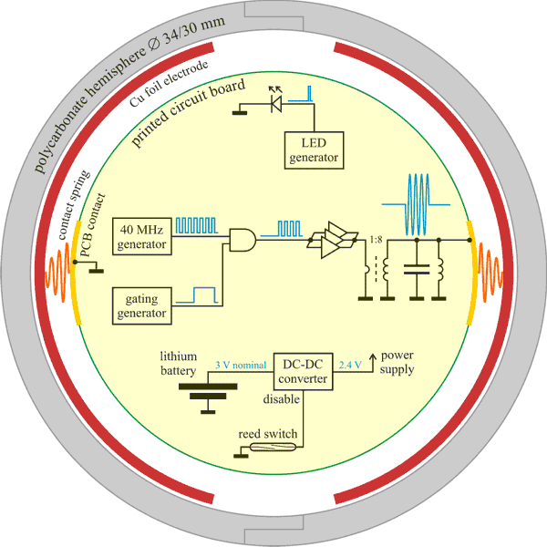
Diagram of the RF ball and its circuitry.
The circuitry of the RF ball
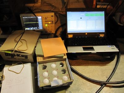
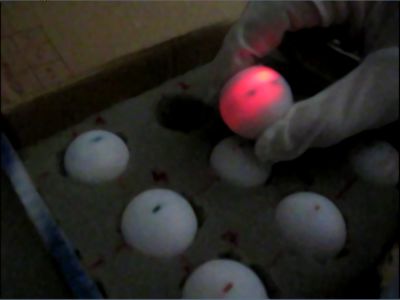
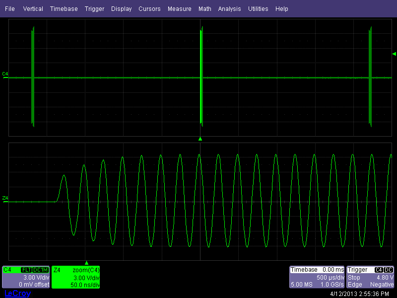
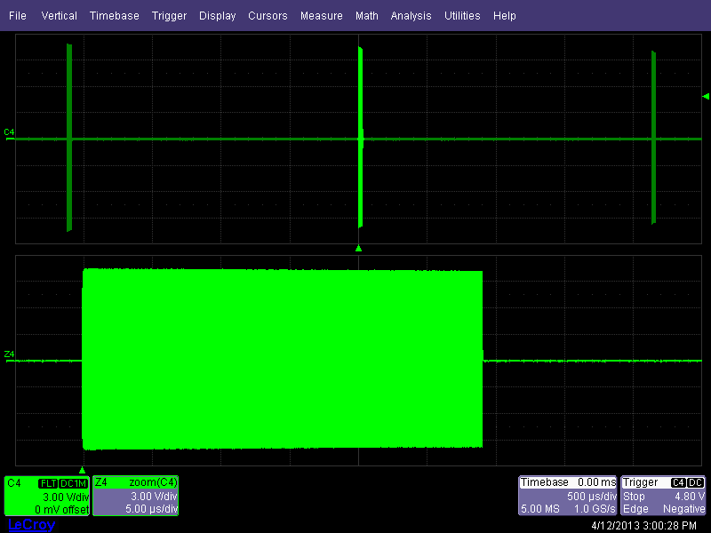
The polycarbonate hemispheres of the RF ball must be joined in a very reliable way, to exclude a catastrophic opening of the ball inside the LHC beam pipe. As the ball during its travel suffers from mechanical shocks, gluing was chosen as the most reliable way of connecting the hemispheres together. The ball electronic circuit with the battery is put inside before this operation, making impossible to re-use the ball once the battery is depleted. Then the ball gets opened to recuperate the electronic circuit, which is equipped with a new battery and put again inside a new ball.To rationalize the usage of RF balls it was important to extend their lifetime to be able to use them many times in the LHC tunnel and to glue the hemispheres in the lab. This was achieved by choosing the battery of as large capacity as it was reasonably possible, minimizing the power consumption of the ball electronics and providing a possibility to turn off the ball circuitry by an external magnetic field. For this purpose the ball electronics is equipped with a small reed switch, which is actuated by putting the ball on top of a small permanent magnet. In this state the electronics is in a standby mode, in which it may stay for months before the battery gets discharged significantly. The prepared balls stay on their magnets until they are used for the tests. Then once taken from the magnetic field they are ready for use. This is confirmed by a LED flashing inside the ball, sufficiently transparent to make the red light visible from the outside. The operation of the RF transmitter is verified systematically before each ball use. Until 2013 it was done in the LHC tunnel with an oscilloscope by bringing its high impedance probe to the tested ball. The capacitive coupling between the ball electrodes and the probe is sufficient to induce a signal at the 100 mVpp level. Starting from 2013 the ball transmitter is tested with a dedicated small probe consisting of two simple electrodes connected to an RF diode detector, driving headphones. Once the tested ball is put between the probing electrodes, the signal induced by the ball transmitter is sufficient to be heard with the headphones. Once the ball operation is not needed any more, it is put back on top of its magnet, which switches the ball to the standby mode.
The RF ball is equipped with two copper foil electrodes, covering most of the internal surface of the hemispheres. The electrodes are driven by a 40 MHz generator accommodated on a printed circuit board inside the ball and powered from a 3 V CR2032 lithium battery (20 mm x 3.2 mm, 240 mAh, 3 g). At this optimum frequency 1 Vpp signal on the ball electrodes yields about 5 mVpp on the LHC BPM button electrodes, which is a threshold for reliable triggering of the BPM system. To compensate for a smaller coupling between the ball and the BPM electrodes when the ball is rolling and provide some safety margin, the operational voltage on the ball electrodes is about 20 Vpp. Production of this amplitude with a minimal power consumption is achieved by making the capacitance of the ball electrodes a part of a resonant circuit, which is driven by a low voltage generator through a step-up RF transformer. The low voltage generator consists of a miniature quartz oscillator followed by three CMOS gates operated in parallel to minimize their overall on resistance required for an efficient drive of the transformer loaded with the resonant circuit. The 40 MHz transmitter is gated with a small duty cycle by an auxiliary generator, switching on the electrode signal for about 30 µs (i.e. some 1200 of 25 ns periods) every some 2 ms, resulting in the duty cycle of 1.5 %. During the off time the ball advances by some 5 mm at the nominal speed of 2.5 m/s, which is still a fraction of the distance of good coupling between the ball and the BPM electrodes (some 20 mm). These gating conditions are close to optimal, as faster gating increases the power consumption due to the more frequent filling of the resonant circuit and longer off time is not possible due to the limited coupling distance between the ball and the BPM electrodes. Unfortunately the quartz oscillator cannot be keyed with the transmitter due to its long turn-on time. This is why gating reduces the overall current consumption less than the gating duty cycle. The ball electronics is powered by a battery through a high efficiency micropower DC-DC converter, lowering and stabilizing the circuit power supply at 2.4 V, at which a smaller current consumption can be achieved. The converter assures also a relaible generator operation with the battery depleted down to 0.6 V.
The ball electronics contains 5 integrated chips, accommodated on 2 sides of a round PCB of about the battery size. The weight of the circuit with the battery constitutes about half of the total weight of the ball ready to use (15 g).